 Login
Login
The IAS XR3000™ has a built in Configurable Logic Controller (CLC). Generally speaking, any type of Logic Controller, monitors inputs and makes decisions based on those inputs to turn on outputs. For a Programmable Logic Controller, the definition of inputs, decision-making logic, and output control is programmed into the PLC using some form of ladder logic.
The XR3000 is the next generation of automation with many features of the first generation of Advanced AutoStart and adds many new ones.
The CLC portion of the IAS XR3000™ can be simply configured via HarvestWatch™ in three simple steps:
- Configure input conditions. The XR3000 supports up to 8 wireless inputs. These inputs are identified automatically by sensor type. An input condition is defined by crossing a configurable threshold. Each input has a high and a low threshold, so that dropping below a certain low temperature, for example could be considered ‘ON’ and rising above a high temperature setting would then be considered “OFF”.
- Configure inputs to control specific outputs. The XR3000™ has 8 wireless inputs and 8 outputs. Each wireless input is configured as to which output is controlled by that input’s “ON”, “OFF” conditions. For example, if Output 1 was being used to turn on a pump, and the desired behavior was to turn on based on either Temperature or Soil Moisture, all of the wireless Temperature, and Soil Moisture sensors would be configured to control Output 1.
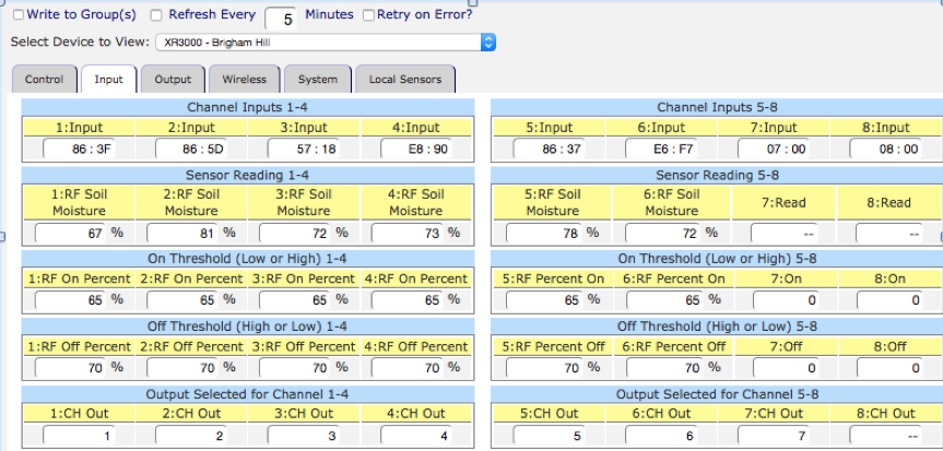
Input Tab
In the Image above, the Step One input conditions are configured to “turn ON” outputs when soil moisture drops below 65%. Step Two is handed by simply taking the default mapping of output to input conditions.
- Configure output behavior. Outputs have various configurable characteristics that come into play when they are being turned “ON” by any wireless input. They can be configured to have a delay before activating, to be exclusive with respect to other outputs, to remain on for a specific time after being activated, etc. And output can also be configured to “follow” the state of any other output, either with or without a delay. This allows for a pump to always be on when any valve is open, for example, or for a valve to be sequenced to turn on at some specific delay after another specific output has been triggered.

Output Tab
The image above shows each output configured to run or be “ON” for 40 minutes based on it’s corresponding input condition. The outputs are all exclusive, meaning only one output should be “ON” at a time. There is also a lockout time specified to allow fairness between outputs. Once an output has run, it will not be “ON” again for at least the lockout period defined. This example is the complete configuration needed to “Configure” the logic to control a multi-zone drip irrigation system where each zone is independent, but all zones should be irrigated at a fixed pressure. Note that in the upper right corner of the tab, 8:CH Trig is defined as “9” meaning output 8 will follow any other output that is on. This turns on the pump, when any zone calls for water.
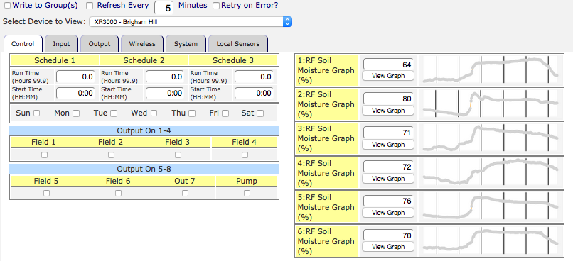
Control Tab
Note that in the Control Tab, we have renamed the Outputs to match the application.
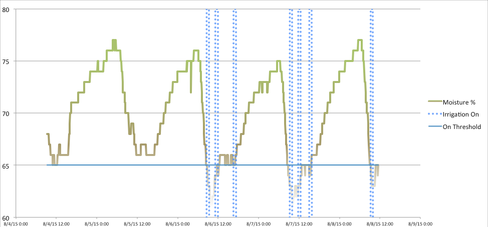
In the image above, showing a graph of the data from Field 1 in our example, you can see that the irrigation is being driven by the soil moisture percentage. When the soil moisture percentage drops below 65% the irrigation is turned on to keep the crops from going into stress.